ucore OS | 实验 1 ucore 的启动过程
练习 1
操作系统镜像文件
ucore.img是如何一步一步生成的?通过执行命令
make V="",使make显示出编译过程中执行的命令:1
2
3
4
5
6
7
8
9
10
11
12
13
14
15
16
17
18
19
20
21
22
23
24
25+ cc kern/init/init.c
gcc -Ikern/init/ -fno-builtin -fno-PIC -Wall -ggdb -m32 -gstabs -nostdinc -fno-stack-protector -Ilibs/ -Ikern/debug/ -Ikern/driver/ -Ikern/trap/ -Ikern/mm/ -c kern/init/init.c -o obj/kern/init/init.o
// 省略相似命令……
+ ld bin/kernel
ld -m elf_i386 -nostdlib -T tools/kernel.ld -o bin/kernel obj/kern/init/init.o obj/kern/libs/stdio.o obj/kern/libs/readline.o obj/kern/debug/panic.o obj/kern/debug/kdebug.o obj/kern/debug/kmonitor.o obj/kern/driver/clock.o obj/kern/driver/console.o obj/kern/driver/picirq.o obj/kern/driver/intr.o obj/kern/trap/trap.o obj/kern/trap/vectors.o obj/kern/trap/trapentry.o obj/kern/mm/pmm.o obj/libs/string.o obj/libs/printfmt.o
+ cc boot/bootasm.S
gcc -Iboot/ -fno-builtin -fno-PIC -Wall -ggdb -m32 -gstabs -nostdinc -fno-stack-protector -Ilibs/ -Os -nostdinc -c boot/bootasm.S -o obj/boot/bootasm.o
// 省略相似命令……
gcc -g -Wall -O2 obj/sign/tools/sign.o -o bin/sign
+ ld bin/bootblock
ld -m elf_i386 -nostdlib -N -e start -Ttext 0x7C00 obj/boot/bootasm.o obj/boot/bootmain.o -o obj/bootblock.o
'obj/bootblock.out' size: 504 bytes
build 512 bytes boot sector: 'bin/bootblock' success!
dd if=/dev/zero of=bin/ucore.img count=10000
10000+0 records in
10000+0 records out
5120000 bytes (5.1 MB, 4.9 MiB) copied, 0.0156548 s, 327 MB/s
dd if=bin/bootblock of=bin/ucore.img conv=notrunc
1+0 records in
1+0 records out
512 bytes copied, 7.1747e-05 s, 7.1 MB/s
dd if=bin/kernel of=bin/ucore.img seek=1 conv=notrunc
154+1 records in
154+1 records out
79036 bytes (79 kB, 77 KiB) copied, 0.000255015 s, 310 MB/s可以看出,生成镜像主要有以下步骤:
使用
gcc编译kern目录和boot下的所有.cC 语言文件和.S汇编代码,可以看到比起平时的编译多出了很多选项:-fno-builtin:表示防止gcc使用自带的内置函数,比如用到的strcpy,如果没有这个选项,gcc会跳过我们的代码,使用它自带的strcpy函数。-nostdinc:表示不要在系统自带的标准库的目录下搜索包含文件,只在-I指定的目录下搜索,这也是为了防止我们自定义的strcpy之类的标准库函数和系统自带的产生冲突。-fno-PIC:表示不要生成 PIC (Position Independent Code)。经过查资料得知,生成 PIC 会使代码体积变大,在 https://github.com/chyyuu/ucore_os_lab/pull/22 可以知道,由于新版本gcc默认启用 PIC,所以会导致生成的bootloader大于 512 字节,无法放进一个扇区中。并且, PIC 需要bootloader正确处理重定位,而 uCore 的bootloader不支持处理重定位,在后续实验中也会产生问题。-fno-stack-protector:同样是为了减小代码体积。启用栈保护的话在函数调用时会增加额外的代码。-Wall:表示打印出所有警告,可以帮我们尽早地发现可能出现的问题。-gstabs和-ggdb:表示生成调试信息,帮助我们后续使用gdb进行调试。-m32:生成 32 位代码。-c:只编译不链接。后面由我们自己使用ld手动链接。
值得注意的是,在编译
bootloader的时候还增加了一个额外的选项:-Os:意思是指示编译器尽可能地优化代码体积,因为bootloader在去掉启动标识符和分区表之后只有 466 字节可用,因此需要尽可能小。
使用
ld进行链接,将目标文件连接成为可执行文件。一个是kernel是操作系统的内核,一个是bootloader用来加载我们编写的操作系统。链接内核的命令是:
1
ld -m elf_i386 -nostdlib -T tools/kernel.ld -o bin/kernel obj/kern/init/init.o ...
-m elf_i386表示模拟 32 位体系。-nostdlib不链接标准库。-T tools/kernel.ld使用tools/kernel.ld链接脚本进行链接。
可以看到
tools/kernel.ld脚本如下:1
2
3
4
5
6
7
8
9
10
11
12
13
14
15
16
17
18
19
20
21
22
23
24
25
26
27
28
29
30
31
32
33
34
35
36
37
38
39
40
41
42
43
44
45
46
47
48
49
50
51
52
53
54
55
56
57
58/* Simple linker script for the JOS kernel.
See the GNU ld 'info' manual ("info ld") to learn the syntax. */
OUTPUT_FORMAT("elf32-i386", "elf32-i386", "elf32-i386")
OUTPUT_ARCH(i386)
ENTRY(kern_init)
SECTIONS {
/* Load the kernel at this address: "." means the current address */
. = 0x100000;
.text : {
*(.text .stub .text.* .gnu.linkonce.t.*)
}
PROVIDE(etext = .); /* Define the 'etext' symbol to this value */
.rodata : {
*(.rodata .rodata.* .gnu.linkonce.r.*)
}
/* Include debugging information in kernel memory */
.stab : {
PROVIDE(__STAB_BEGIN__ = .);
*(.stab);
PROVIDE(__STAB_END__ = .);
BYTE(0) /* Force the linker to allocate space
for this section */
}
.stabstr : {
PROVIDE(__STABSTR_BEGIN__ = .);
*(.stabstr);
PROVIDE(__STABSTR_END__ = .);
BYTE(0) /* Force the linker to allocate space
for this section */
}
/* Adjust the address for the data segment to the next page */
. = ALIGN(0x1000);
/* The data segment */
.data : {
*(.data)
}
PROVIDE(edata = .);
.bss : {
*(.bss)
}
PROVIDE(end = .);
/DISCARD/ : {
*(.eh_frame .note.GNU-stack)
}
}比较重要的部分有:
- 指定了程序起始地址为
0x100000。 - 导出了
etext、edata和end地址供后续 C 语言程序使用,以便能够正确初始化内存。 - 加入内核调试信息。
而链接
bootloader的命令是:1
ld -m elf_i386 -nostdlib -N -e start -Ttext 0x7C00 obj/boot/bootasm.o obj/boot/bootmain.o -o obj/bootblock.o
和链接内核的有少许不同:
-N:将text段设置为可读可写,不对齐data段,不链接动态库。-e:程序的入口是start标签。-Ttext 0x7C00:程序的text段从0x7C00开始,因为 BIOS 会将bootloader放在0x7C00处开始执行。
对
bootloader签名,使得操作系统可以正常引导。即在bootloader第 511、512 个字节处要写入0x55和0xAA。使用
dd命令生成镜像。- 首先生成一个 10000 个扇区的全零的镜像。
- 然后在第一个扇区(扇区 0)写入大小为 512 字节的
bootloader。 - 然后在
bootloader之后(扇区 1)写入真正的操作系统内核。
一个被系统认为是符合规范的硬盘主引导扇区的特征是什么?
- 大小为 512 字节。
- 最后两个字节为
0x55和0xAA。 - 由不超过 466 字节的启动代码和不超过 64 字节的硬盘分区表加上两个字节的结束符
0x55AA组成。
练习 2
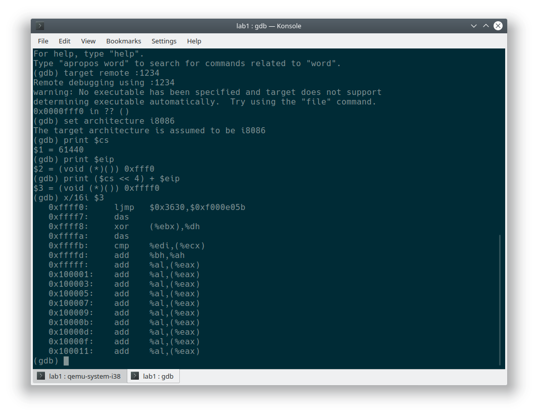
- 从 CPU 加电后执行的第一条指令开始,单步跟踪 BIOS 的执行。
操作步骤:
执行
make命令生成可启动镜像。输入命令
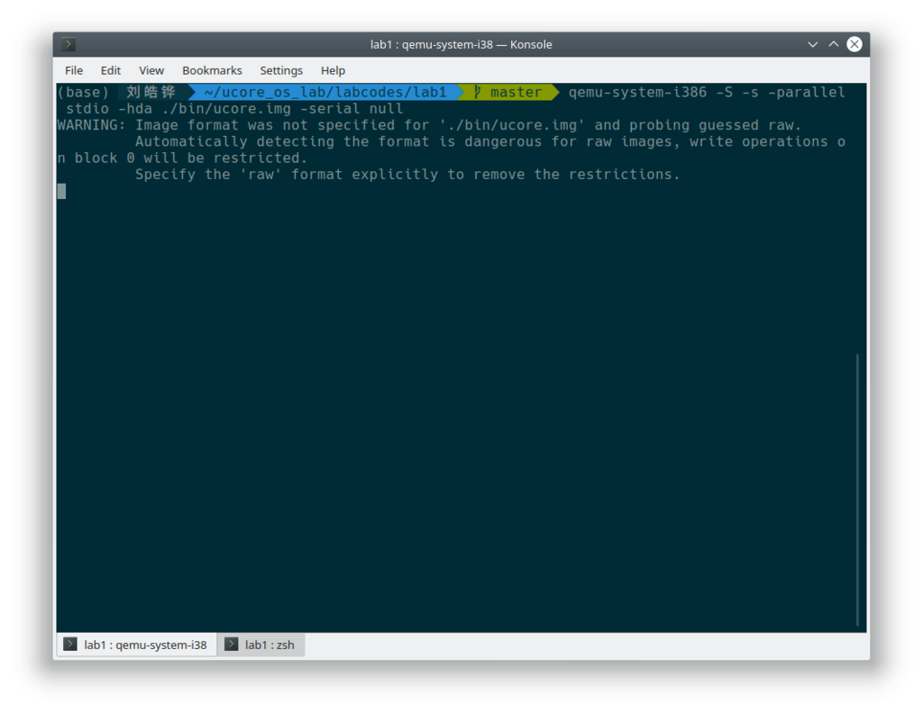
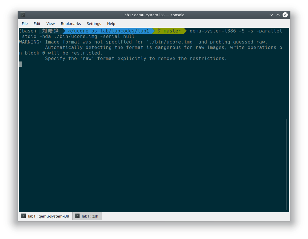
qemu-system-i386 -S -s -parallel stdio -hda ./bin/ucore.img -serial null启动qemu模拟器。-s表示在tcp::1234打开GDB调试服务器。-S代表开机后暂停 CPU 执行,只有用户输入命令之后才开始执行。-hda指定了硬盘的镜像。-parallel和-serial分别指定并行口和串行口的输出重定向位置。
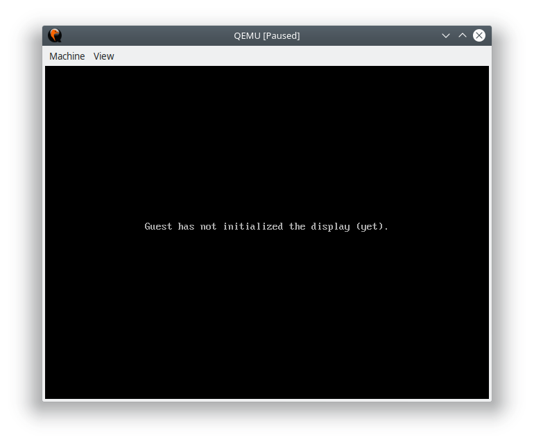
可以看到
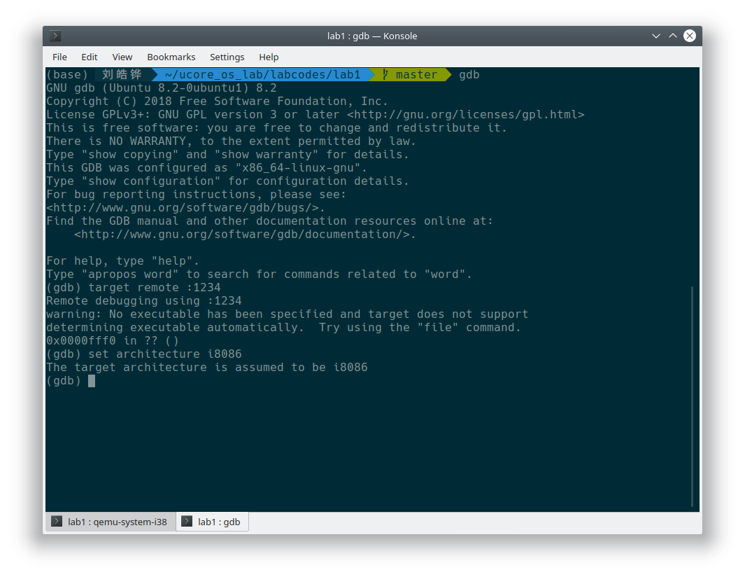
qemu启动后没有继续加载,而是暂停了 CPU 的执行。启动
gdb,输入target remote :1234连接到qemu准备调试,并且输入set architecture i8086指示qemu现在的可执行代码是 16 位的,因为 BIOS 代码是 16 位的。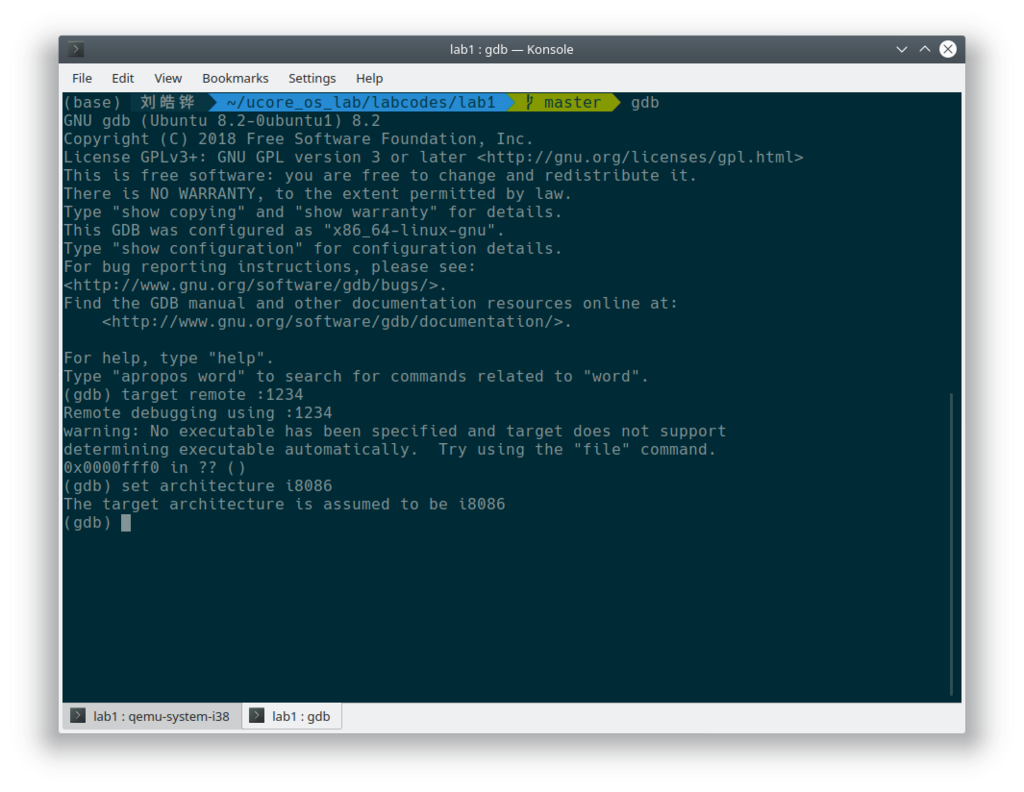
准备完成之后。
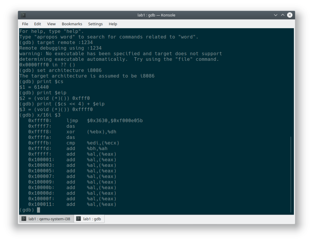
输入命令
1
2
3
define hook-stop
x/i $pc
end在每次暂停执行代码时强制反汇编当前命令。
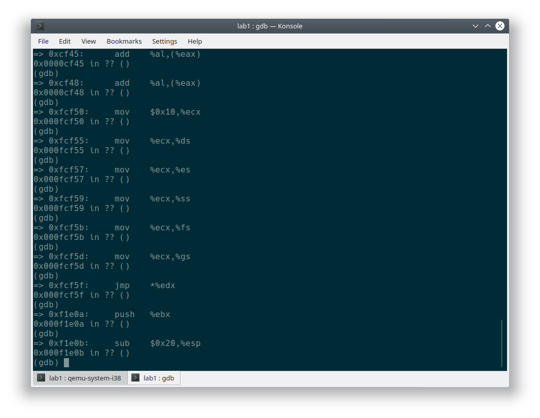
输入
stepi开始单步跟踪 BIOS 执行过程,运行结果如下图所示: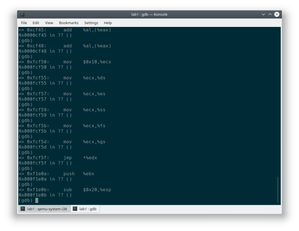
在初始化位置
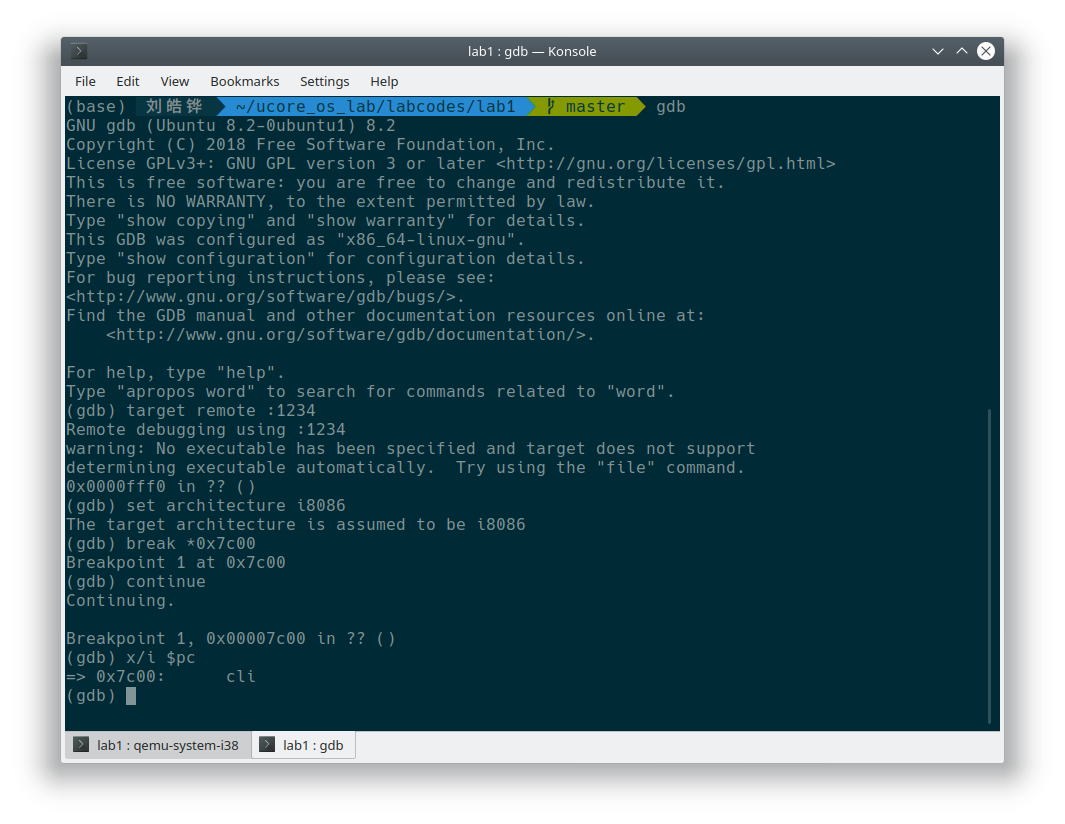
0x7c00设置实地址断点,测试断点正常。- 按照上面的操作启动
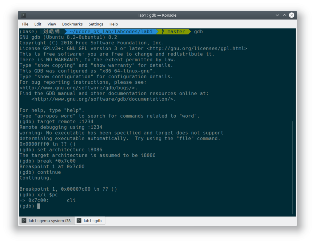
qemu和gdb调试之后,输入break *0x7c00在地址0x7c00处设下断点。 - 然后输入
continue让 CPU 正常执行。 - 可以看到,当 CPU 执行到
0x7c00处时,遇到了断点,自动暂停执行。此时输入x/i $pc进行反汇编,正是bootloader.S的第一条指令cli。
- 按照上面的操作启动
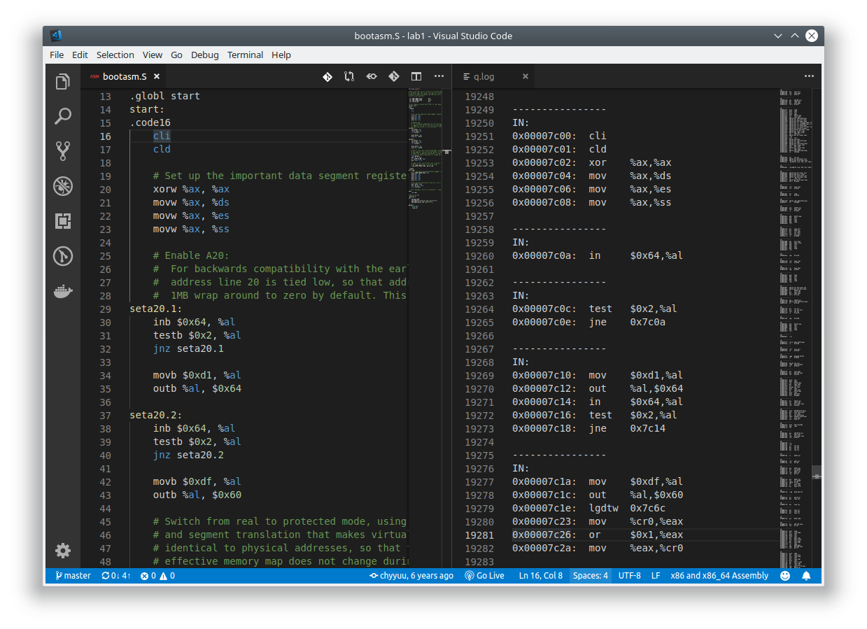
在调用 qemu 时增加
-d in_asm -D q.log参数,便可以将运行的汇编指令保存在q.log中。 将执行的汇编代码与bootasm.S和bootblock.asm进行比较,看看二者是否一致。- 执行命令
qemu-system-i386 -d in_asm -D q.log -S -s -parallel stdio -hda ./bin/ucore.img -serial null启动qemu并记录执行的汇编代码到q.log中。 - 执行命令后,用文本编辑器打开
q.log文件和bootasm.S进行比较,定位到地址0x00007c00处可以发现它们是一致的。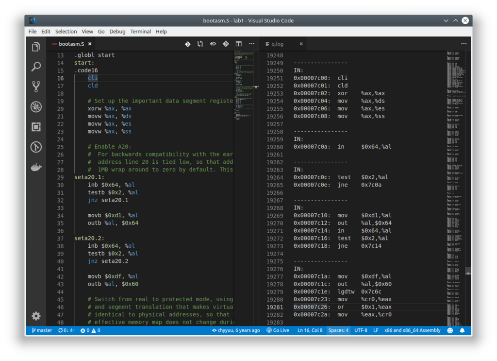
- 执行命令
练习 3
BIOS 将通过读取硬盘主引导扇区到内存,并转跳到对应内存中的位置执行 bootloader。请分析 bootloader 是如何完成从实模式进入保护模式的。
1 | #include <asm.h> |
启动过程如下:
- 关闭中断,清空主要寄存器。
- 打开 A20 模式,通过控制 8042 键盘控制器实现。
- 设置全局描述符,将全局描述符表的地址和大小加载到寄存器中。
- 设置
CR0寄存器$CR0_PE_ON位,启动保护模式。 - 然后在 32 位模式下,设置好段寄存器和栈寄存器,跳转到
bootmain也就是加载内核 ELF 的程序。
练习 4
分析 bootloader 加载 ELF 格式的 OS 的过程。
bootloader是如何读取硬盘扇区的?bootloader主要通过readsect()和waitdisk()两个函数进行硬盘扇区的读取。1
2
3
4
5
6
7
8
9
10
11
12
13
14
15
16
17
18static void
readsect(void *dst, uint32_t secno) {
// wait for disk to be ready
waitdisk();
outb(0x1F2, 1); // count = 1
outb(0x1F3, secno & 0xFF);
outb(0x1F4, (secno >> 8) & 0xFF);
outb(0x1F5, (secno >> 16) & 0xFF);
outb(0x1F6, ((secno >> 24) & 0xF) | 0xE0);
outb(0x1F7, 0x20); // cmd 0x20 - read sectors
// wait for disk to be ready
waitdisk();
// read a sector
insl(0x1F0, dst, SECTSIZE / 4);
}首先等待磁盘控制器准备好,然后写入控制信息,
0x1F2是要读取的扇区数,0x1F3到0x1F6存储着要进行操作的扇区号码(小端存储),然后向0x1F7发送读取指令。等磁盘再次就绪后,通过反复调用insl指令SECTSIZE / 4次,将磁盘内容以 4 字节为一组读取到内存中。基于这两个函数,
bootloader还有函数readseg()包装了一下基本操作,用以读取多个扇区。1
2
3
4
5
6
7
8
9
10
11
12
13
14
15
16
17static void
readseg(uintptr_t va, uint32_t count, uint32_t offset) {
uintptr_t end_va = va + count;
// round down to sector boundary
va -= offset % SECTSIZE;
// translate from bytes to sectors; kernel starts at sector 1
uint32_t secno = (offset / SECTSIZE) + 1;
// If this is too slow, we could read lots of sectors at a time.
// We'd write more to memory than asked, but it doesn't matter --
// we load in increasing order.
for (; va < end_va; va += SECTSIZE, secno ++) {
readsect((void *)va, secno);
}
}函数的作用是从磁盘的
offset字节处开始读取count个字节到va指向的虚拟地址中。bootloader是如何加载 ELF 格式的 OS?1
2
3
4
5
6
7
8
9
10
11
12
13
14
15
16
17
18
19
20
21
22
23
24
25
26
27
28
29
30void
bootmain(void) {
// read the 1st page off disk
readseg((uintptr_t)ELFHDR, SECTSIZE * 8, 0);
// is this a valid ELF?
if (ELFHDR->e_magic != ELF_MAGIC) {
goto bad;
}
struct proghdr *ph, *eph;
// load each program segment (ignores ph flags)
ph = (struct proghdr *)((uintptr_t)ELFHDR + ELFHDR->e_phoff);
eph = ph + ELFHDR->e_phnum;
for (; ph < eph; ph ++) {
readseg(ph->p_va & 0xFFFFFF, ph->p_memsz, ph->p_offset);
}
// call the entry point from the ELF header
// note: does not return
((void (*)(void))(ELFHDR->e_entry & 0xFFFFFF))();
bad:
outw(0x8A00, 0x8A00);
outw(0x8A00, 0x8E00);
/* do nothing */
while (1);
}1
2
3
4
5
6
7
8
9
10
11
12
13
14
15
16
17struct elfhdr {
uint32_t e_magic; // must equal ELF_MAGIC
uint8_t e_elf[12];
uint16_t e_type; // 1=relocatable, 2=executable, 3=shared object, 4=core image
uint16_t e_machine; // 3=x86, 4=68K, etc.
uint32_t e_version; // file version, always 1
uint32_t e_entry; // entry point if executable
uint32_t e_phoff; // file position of program header or 0
uint32_t e_shoff; // file position of section header or 0
uint32_t e_flags; // architecture-specific flags, usually 0
uint16_t e_ehsize; // size of this elf header
uint16_t e_phentsize; // size of an entry in program header
uint16_t e_phnum; // number of entries in program header or 0
uint16_t e_shentsize; // size of an entry in section header
uint16_t e_shnum; // number of entries in section header or 0
uint16_t e_shstrndx; // section number that contains section name strings
};首先函数加载 ELF 的头部到内存中,判断魔数是否合法,如果合法,则开始读取 ELF 中的每一段到内存中的相应位置。
1
2
3
4
5
6
7
8
9
10
struct proghdr {
uint32_t p_type; // loadable code or data, dynamic linking info,etc.
uint32_t p_offset; // file offset of segment
uint32_t p_va; // virtual address to map segment
uint32_t p_pa; // physical address, not used
uint32_t p_filesz; // size of segment in file
uint32_t p_memsz; // size of segment in memory (bigger if contains bss)
uint32_t p_flags; // read/write/execute bits
uint32_t p_align; // required alignment, invariably hardware page size
};ELF 段的信息由
proghdr结构指示,第一个proghdr位于e_phoff偏移量,数量则是e_phnum,其中p_va指示段在内存中的虚拟地址,p_memsz标志了段的大小,p_offset则是相对于 ELF 文件的偏移量。将每一段都读取到了内存中的相应位置之后,就跳转到 ELF 头部中
e_entry所指示的入口地址执行,控制权移交给操作系统。
练习 5
实现函数调用堆栈跟踪函数 print_stackframe()。
通过附录得知,在每个函数体的开始,编译器都会插入如下汇编代码:
1 | pushl %ebp |
这样在程序执行到一个函数的实际指令前,已经有以下数据顺序入栈:参数、返回地址、ebp 寄存器。由此得到类似如下的栈结构(以 cdecl 方式为例):
1 | +| 栈底方向 | 高位地址 |
此时 ebp 处于非常重要的地位,因为给 ebp 赋值之前,原 ebp 值已经被压栈(位于栈顶),而新的 ebp 又恰恰指向栈顶。从函数堆栈结构可以知道,通过 ebp 寄存器中的地址向上可以获得返回地址和参数,向下可以获取到局部变量,通过它本身可以获取到上一层函数调用的 ebp 地址。
根据这个结构,就可以写出显示函数调用堆栈的函数如下了:
1 | void |
需要注意的是在遇到 ebp == 0 的情况下,已经没有上一层的函数调用了,应该终止调用。
完成函数编写之后,执行 make qemu 查看执行结果: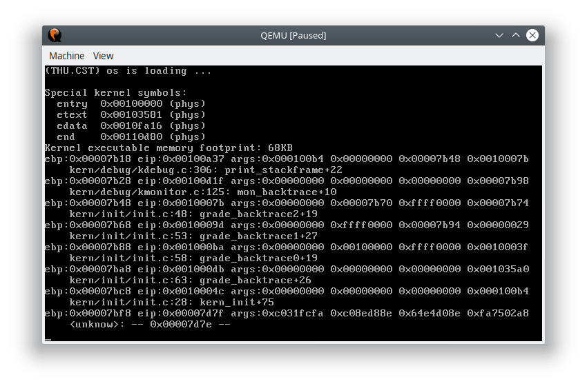
输出最后一层是函数调用的最深层,也就是第一个被调用的函数 kern_init() 因为栈地址是从 0x7c00 开始,在从 bootmain() 函数调用到内核初始化函数 kern_init() 时有 call 指令,0x7bfc 地址存放的是返回地址,而编译器在函数体的头部都会插入:
1 | pushl %ebp |
通过查看 kernel.asm 也可以确认: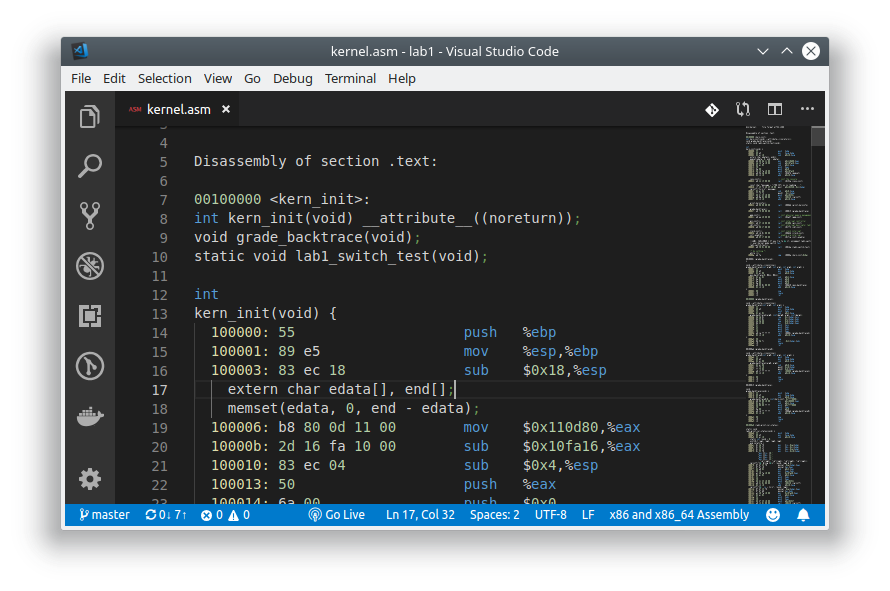 于是此时栈顶地址变为
 0x7bf8,而这个地址赋值给了 ebp 寄存器,我们就看到了 ebp 寄存器的内容是 0x7bf8 了。这个函数调用没有参数,后面的参数没有意义。
练习 6
完善中断初始化和处理。
中断向量表中一个表项占多少字节?其中哪几位代表中断处理代码的入口?
查看
struct gatedesc定义如下:1
2
3
4
5
6
7
8
9
10
11struct gatedesc {
unsigned gd_off_15_0 : 16; // low 16 bits of offset in segment
unsigned gd_ss : 16; // segment selector
unsigned gd_args : 5; // # args, 0 for interrupt/trap gates
unsigned gd_rsv1 : 3; // reserved(should be zero I guess)
unsigned gd_type : 4; // type(STS_{TG,IG32,TG32})
unsigned gd_s : 1; // must be 0 (system)
unsigned gd_dpl : 2; // descriptor(meaning new) privilege level
unsigned gd_p : 1; // Present
unsigned gd_off_31_16 : 16; // high bits of offset in segment
};可以看到一个
struct gatedesc占用 8 字节,其中低 2 字节和高 2 字节拼接成段偏移的低 16 位和高 16 位,2-3 字节则是段选择子。请编程完善
kern/trap/trap.c中对中断向量表进行初始化的函数idt_init。在idt_init函数 中,依次对所有中断入口进行初始化。使用mmu.h中的SETGATE宏,填充idt数组内容。注意除了系统调用中断 (T_SYSCALL)以外,其它中断均使用中断门描述符,权限为内核态权限;而系统调用中断使用异常,权限为用户态权限。每个中断的入口由tools/vectors.c生成,使用trap.c中声明的vectors数组即可。代码如下:
1
2
3
4
5
6
7
8
9
10
11
12void
idt_init(void) {
extern uintptr_t __vectors[];
for (int i = 0; i < sizeof(idt) / sizeof(struct gatedesc); ++i) {
SETGATE(idt[i], 0, GD_KTEXT, __vectors[i], DPL_KERNEL);
}
SETGATE(idt[T_SYSCALL], 1, GD_KTEXT, __vectors[T_SYSCALL], DPL_USER);
SETGATE(idt[T_SWITCH_TOK], 0, GD_KTEXT, __vectors[T_SWITCH_TOK], DPL_USER);
lidt(&idt_pd);
}使用
SETGATE宏设置好中断描述表,调用lidt命令将其加载,以后遇到中断时就会进入我们的中断处理程序。请编程完善
trap.c中的中断处理函数trap(),在对时钟中断进行处理的部分填写trap()函数中处理时钟中断的部分,使操作系统每遇到 100 次时钟中断后,调用print_ticks()子程序,向 屏幕上打印一行文字“100 ticks”。 可以知道定时器中断的中断号是IRQ_TIMER,所以在switch块中找到IRQ_TIMER填入相关代码。代码很简单:1
2
3
4
5
6
7
8
9static void
trap_dispatch(struct trapframe *tf) {
char c;
switch (tf->tf_trapno) {
case IRQ_OFFSET + IRQ_TIMER:
if ((++ticks) % TICK_NUM == 0) print_ticks();
break;
// ...
}
完成代码后,执行 make qemu ,可以看到大约每隔一段时间就会输出一行 “100 ticks”,同时屏幕上会回显键盘按键。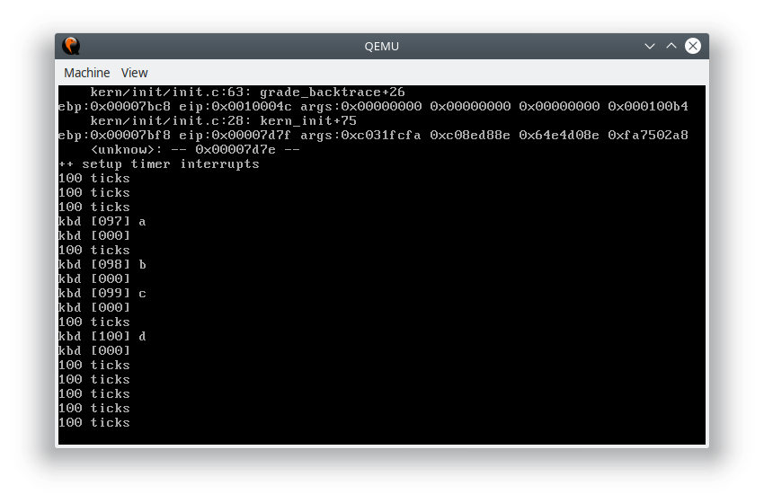
扩展练习
这一部分的代码注释比较少,需要自己理解的部分较多。
由于切换特权级别的操作需要通过更改 CS 段寄存器来实现,但是 CS 段寄存器不能直接修改。在中断发生时,硬件会自动将 CS 、EIP、EFLAGS 和 ERRCODE 压栈,中断返回时从栈中恢复这些寄存器的值。因此,必须通过 iret 指令修改 CS 段寄存器中的值,也就是在中断处理程序中,必须更改 struct trapframe 中的 tf_cs 字段才能实现特权级的转换。对于 SS 段选择子寄存器而言也是一样的,要更改它的值必须通过修改 struct trapframe 来实现。
需要注意的是 iret 指令在不同情况下表现是不同的。查阅资料得:
1 | if(OperandSize == 32) { |
从上面的伪代码可以看出,如果在中断返回时,代码段从特权级较高的一层转换到了特权级较低的一层,iret 指令还会将 SS 和 ESP 出栈覆盖原来的值,也就是说在从内核态切换到用户态的时候我们还要设置 tf_ss 到用户段空间中,确保栈段选择子的 RPL 与代码段选择子的 RPL 相同,否则会引发 General Protection 异常。
1 | struct trapframe switchk2u, *switchu2k; |
从以上代码可以看出,从内核态切换到用户态时要先修改各段寄存器,然后将 tf_esp 设置为原来的栈顶,最后更改 tf_eflags 的特权级。
1 | +| 栈底方向 | 高位地址 |
最后一行的
1 | *((uint32_t *)tf - 1) = (uint32_t) &switchk2u; |
比较巧妙,在这句执行完毕后,函数就返回到了
1 | pushl %esp |
而此时的栈变为了
1 | +| 栈底方向 | 高位地址 |
所以,ESP 马上就会被 switchk2u 的地址所覆盖,接下来寄存器的出栈,和段寄存器的修改,都会以我们刚刚修改的 struct trapframe switchk2u 的内容为准,因此也就完成了从内核态到用户态的切换。在 gdb 中也可以观察到: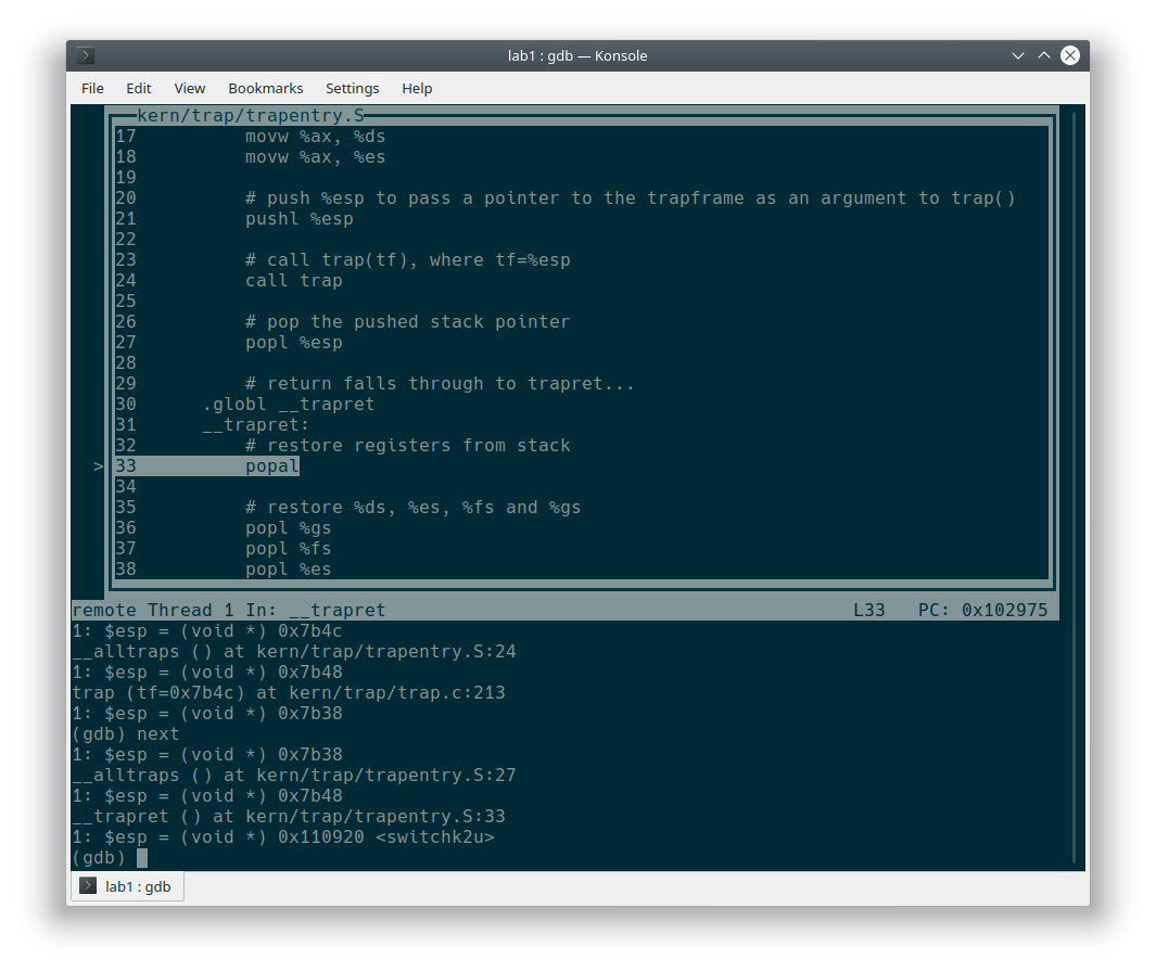
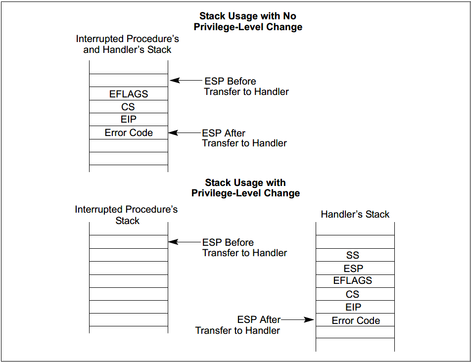
而在用户态切换到内核态的时候,中断处理例程的 CS 段选择子权限高于发起中断的程序,所以会发生栈的切换,struct trapframe 中的 tf_esp 就是原来的 ESP 寄存器,而 SS 段选择子已经在发生中断的时候切换到内核的段选择子了,无需我们手动设定。同时,iret 返回时,tf_cs 的特权级也已经变成了内核特权级,没有发生特权级的转换,所以 SS 和 ESP 都不会被栈的内容覆盖,也无需设定了。
1 | struct trapframe switchk2u, *switchu2k; |
代码和切换到用户态类似,只不过少了 tf_ss 和 tf_esp 的拷贝。
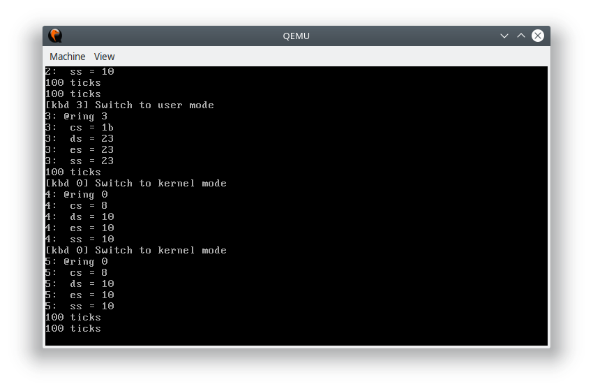
完成代码后,执行 make grade ,可以看出我们的实现是正确的:
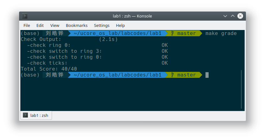
从上面的分析可以看出,调用切换到用户态的函数时,会多 pop 两个 32 位数,所以在调用前要先保护栈,不过由于在中断处理程序中我们已经将栈指针改到别的地方去了,所以其实不太需要。
增加一个系统调用用来获取当前时钟计数值,则是通过 T_SYSCALL 中断来实现,系统调用采用 EAX 寄存器传递调用号,这里就取 1 作为获取时钟计数的调用号了:
1 | // kern/init/init.c |
最后通过键盘上的“0”和“3”切换用户态和内核态的代码就是在主循环中加入:
1 | while (1) { |
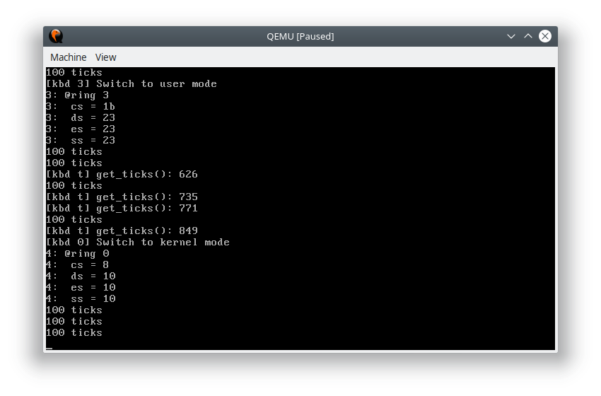
按下 “3” 后,切换到用户态,按下 “0” 后,切换到内核态,按下“t”后就获得当前时钟计数值并输出。
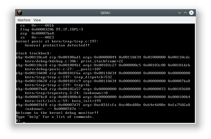
值得注意的是,在内核态中调用切换到内核态的函数不会有任何作用;但如果在用户态调用切换到用户态模式,则会导致权限不足引发 General Proctection: